Wednesday, May 9, 2007

Manjung Simulator Software Count

Non-Modelling Software (Not Under Escrow)
Operating System
  • Microsoft XP Professional
Office Suite
  • Microsoft Office Professional Office Suite
Development Tools
  • Microsoft Visual Studio DotNet Professional
  • Intel Fortran Compiler
Operator Consoles
  • ABB OperateIT
Hard Panel Soft Simulation
  • GE Dataview
Non-Modelling Software (Under Escrow)
SEMS XP Software Development System
  • CAD Editor GLCAD
  • Code Generators GRIPS & LIDO
  • I&C Translator for ABB Function Plans
  • Configuration Management System CMS
  • Software Integration Environment incl. Revision Control System
  • Pre-Compilers for FORTRAN- and C-Langauge
SEMS XP Executive (Run-Time System)
  • Simulator Main Process incl. all DLL’s
  • SEMS XP Interfaces incl. OPC Interface and tools
SEMS XP User-/Instructor-Interface
  • Process Supervisor Client
  • Trend Client
  • Numerical Display Client
  • Intervention Client
  • Event Trigger Client
  • Threshold Client
  • CAEP Client
  • GLCAD Viewer Client
  • Logging Client
  • Soft Panel Client
Modelling Software

Process Models


  • The entire plant will be divided in Simulation Sub-systems. One CAD drawing per sub system. The sub systems would be defined during the design phase. For each sub system, a system module, a module which simulates the electrical devise and a transmitter program as well as ADD- and LOAD-files will be generated from the CAD drawing.
I&C Models
  • One CAD drawing per logic diagram downloaded and translated from OperateIT logic diagram

Manjung Simulator Hardware Count

Simulation Computer
  • The Simulation Computer will be configured according to the requirements of the simulator system specification. The Contractor offers HP xw6200 Workstation (or comparable) with 19” TFT HP L1940 (or comparable).
Instructor Station (IS)
  • The Instructor Station software is designed in the state of the art client-server technology. Each feature is available as a client at the instructor station. A full collection of the clients is bundled into an instructor station software suite to provide all the features needed to conveniently conduct a training session. The Contractor offers HP Compaq DC7600 (or comparable) with two 21” Samsung SyncMaster 214T (or comparable).
Operator Stations
  • The Operator stations are designed to run the Operate IT software. 6 (six) stations for the operators, 2 (two) stations for the supervisors and 1 (one) station for the connection to the Unit3 are configured. The Contractor offers HP DC7600 (or comparable) with two 21” Samsung SyncMaster 214T (or comparable) with 2 (two) 21” Samsung SyncMaster 214T (or comparable).
Simulator Engineering Workstation (SEWS)
  • The engineering station is configured to support the maintenance of the simulator software. The necessary tools and compiler are available. The Contractor offers HP Compaq DC7600 (or comparable) with 19” TFT HP L1940 (or comparable).
Domain Controler
  • The Contractor offers HP Compaq DC7600 (or comparable) with 19” TFT HP L1940 (or comparable).
Historian Server
  • The Contractor offers HP Compaq DC7600 (or comparable) with 19” TFT HP L1940 (or comparable).
Real Time Data Server (RTDS)
  • The Contractor offers HP Compaq DC7600 (or comparable) with 19” TFT HP L1940 (or comparable).
Configuration Server
  • The Contractor offers HP Compaq DC7600 (or comparable) with 19” TFT HP L1940 (or comparable).
Tablet PC
  • The Contractor offers HP TABLET TC4200 (or comparable) as remote instructor station.
Big Screen Display / Soft Panel
  • The big screen display / Soft Panel is configured as an additional operator facility with its own projector. The Contractor offers HP Compaq DC7600 (or comparable) with projector HP VP6325.
Printers
  • The Contractor offers HP Laserjet 4250 A4 (or comparable) as black and white printer and HP Color Laserjet 9500N A3 PAR NIC as colour printer.
The Network
  • All simulator hardware components are attached to each other via a central 12 port 1000/100 Mbit/s auto sensing hub switch. The subsystems (IS, Plant Operation, Server etc.) are either directly attached to the switch or are linked through a local fast Ethernet (100/10 Mbit/s) hub. The Tablet PC is attached to a wireless access point.
Uninterruptable Power Supply
  • The Contractor offers GE LanPro 15-31 (or comparable).

Wednesday, April 25, 2007

Introduction


  • In order to meet the nation’s demand in the new millennium, Tenaga Nasional Berhad has designed Stesen Janaelektrik Manjung with capacity of 3 x 700 MW (2100MW) coal fired power plant. At present, Stesen Janaelektrik Manjung will be operating as Independent Power Plant of TNB and will be known as TNB Janamanjung Sdn. Bhd. which is fully owned by Tenaga Nasional Berhad. It is required to supply electric power to TNB via a Power Purchase Agreement (PPA).
  • TNB Janamanjung is also operating as a strategic business enterprise (SBE) under the Generation Division of TNB.The responsibility comes along; all Stesen Janaelektrik Manjung staff are expected to perform up to the required competency level. Every tripping at the station will cost the loss of revenue millions per day/unit. Hence, these incidents can be reduced through proper training programs and services provided.
  • In line with that, Tenaga Nasional Berhad agreed fo TNB Janamanjung to undertake a project to develop, construct and commission a full-scale real time PC-based simulator base on the actual 3 X 700 MW coal fired Stesen Janaelektrik Manjung. This simulator system will be used to retrain and upgrade the competency and capability skills of Stesen Janaelektrik Manjung technical staffs. The project has been awarded to NJSB-RDE JV and kick-off date was on 3rd July 2006. The 20 months project will be completed on 3rd March 2008

Simulator Definition

  • A simulator is a complex system of hardware and software packages assembled and configured according to each customer's specific requirements.
  • A power station training simulator is a training tool designed to replicate the steady state and dynamic responses of a power station to operator actions. In its simplest form, a simulator is a combination of:
  • mathematical models of the plant that "trick" a control system into thinking it is controlling real plant control system emulation man-machine interface. There are several type of simulators :

1. Replica power plant simulators
  • Replica power plant simulators with emulated controls and MMI
  • Replica power plant simulators with stimulated controls and MMI
  • Replica power plant simulators with hybrid controls and MMI

2. Generic simulators

3. Part task simulators

Replica power plant simulators with emulated controls and MMI


  • Replica simulator closely simulates the reference plant configuration, control system, operator interface, and information system
  • In emulation type simulator the functions of the reference plant control system and Human Machine Interface (operator interface) are simulated using alternative or equivalent off-the-shelf open systems hardware and software and VDU based graphics systems to reproduce the HMI functions.

Replica power plant simulators with stimulated controls and MMI

  • In the stimulation type simulator the control system and the HMI are simulated by using the same control system and HMI as in the reference plant. (The hardware and software for the HMI and control system are same as in the real plant).

Replica power plant simulators with hybrid controls and MMI

  • In the hybrid type simulator the control system and the HMI used are the same as in the reference plant but the hardware to perform the function is different or emulated. (The software for the HMI and control system are same as in the real plant but the hardware eg. I/O card is different or been emulated).

Simulator Principle Function

  1. To enable experienced operating and maintenance staffs to familiarize themselves with the reference plant control system and operator interface before being required to operate an maintain the existing reference plant system;
  2. To train new operators in the details of the reference plant and operating and maintenance procedures;
  3. To provide revision for experienced operations and maintenance personnel (refresher training); and
  4. To test control system configurations and graphics.
  5. To enhance reference plant personnel particularly operations competency level.
  6. To assist the reference plant top management in implementing succession planning that includes training and certificating a Patrolman identified to take over a Unit Operator.
  7. To develop a competency database those complements and add value to the Human Resource requirements.
  8. To assist the reference plant top management in developing career path and providing motivation for the staff of the reference plant.
  9. To enhance the bottom line of the reference plant that includes simulating a reference plant malfunction and near misses.

Simulator Major Components And Its Functions


Simulation Computer / Server
  • The server is the master of the simulator. It stores all the process models, logic and controls of the simulation system.The server controls and synchronises operation of the simulator components which includes main executive functions:
  1. Communicates via an Ethernet link to clients.
  2. Manages simulation calculation, real time data storage and exchange management.
  3. Schedule simulator cycles so that all clients remain synchronised.
  4. Ensure data is exchanged between real-time modules at the correct time and in the correct sequence.
  5. Process malfunction scenarios and single malfunctions from the instructor.
  6. Saves/Loads IC/Snapshot or backtrack and Replay
  7. Alarm signalling.

Simulator Major Components And Its Functions


Instructor Station
  • The Instructor Station is the user interface for the Simulator. It provides access to the simulator instructor functions through a GUI and displays a variety of information covering simulator data, status, and confirmation of operator action.
  • Typical instructor station function includes:
  1. Selects Simulator Operating Mode
  2. Recall Backtrack Record State.
  3. Initial Condition Management
  4. Malfunction Management
  5. Trip Inhibit
  6. Select Simulation Speed
  7. System Maintenance Functions
  8. Database Functions
  9. Video Trend Display Functions
  10. Training Exercise Operations
  11. Diagnostic Functions

Simulator Major Components And Its Functions

Simulator Engineering Workstation (SEWS)
  • Any modification of the simulation system is made through EWS. Before the modification is implemented in the simulator, it will be tested in the EWS. Typical EWS function includes:
  1. Logic modification
  2. Malfunction creation
  3. Process tuning

Simulator Major Components And Its Functions


Hard Panel
  • Hard Panel is used when there is requirement from the customer. Some prefer hard panel to instill "what you see is what you get" feeling in simulator. Some people think hard panel soft simulation is adequate. Current trend is more people opt for hard panel soft simulation since the operation in control room nowadays use normal PC and a lot of thing have been migrated to software.

Soft Panel

  • The Mimic Client design approach focuses on ease of use and the ability to display and ease navigate complex Panel Mimics with fast update and realistic operation of panel input. In interactive mode the Mimic Client uses panel mimics to operate the simulator without hard panel. In non-interactive mode the Mimic Client show the status of the output devices.
  • Panel Mimics are replications of control desk and panel sections. All meters, recorders, push buttons, switches, lamps, and potentiometers are shown in a realistic symbol representation. The actual status of panel objects is shown, e.g. by color change, blinking etc. Panel Mimics don't show the contents of displays.Typically a top level panel mimic shows an overview of the panel from which a particular panel mimic can be selected.


Simulator Functional Element

ProModeller
  • Normally the Promodeller consists of many DLL modules linked by the master, but it can be an executable module as a client connecting to the Master via Ethernet by the customers' request.The plant process models are simulated with the Promodeller. It is organised as an integrated set of functional units:
  1. Graphical User Interface (GUI) when runs in stand-alone
  2. Model Calculation
  3. Simulation Configuration Builder
  4. C/C++ source code generation based on the plant network configuration
  5. Database Access
  6. Simulation Model Libraries
  7. Simulation Configuration Builder

Simulator Functional Element

Logic Display
  • The Logic Display module is used to display logic sheets which run time dynamic behaviour. Users can use this module to debug those sheets previously generated by the off-line module (“TSLogic”)The LogicDisplay as a client is connected to the Master via Ethernet

Simulator Functional Element

Synchroscope
  • The Synchroscope module emulates hard synchroscope functionality by display bus voltages, frequencies, turbine speed and phase needle rotation. It indicates when synchronisation is permitted and when operator can close circuit breaker. Synchroscope as a client is connected to the Master via Ethernet

Simulator Functional Element

DCS Client
  • Generally the DCSClient is a DLL module linked by the master, but it can be an executable module as a client connecting to the Master via Ethernet by the customers' request.A typical DCS Client module is a link between the Master and the DCS Server, which communicates with DCS and is written by calling DCS API supplied by the DCS vendor. The DCS Client transfers DCS signals between the Master and the DCS Server.

Simulator Functional Element


IO Client
  • The IOClient module interfaces with third part hardware IO systems (panels). It initiates the requests to scan any input data (Digital and Analog) from panels and to send out applicable new I/O output data (Digital and Analog) to panel using TCP/IP via Ethernet.

Simulator Functional Element

Emu DCS
  • The Emu DCS (Emulated DCS) module is only applied to the emulated simulator. It acts as a client connecting to the Master via Ethernet. The EmuDCS emulates the functions of DCS owned by DCS vendor. Normally the customer specifies what kind of DCS need to be emulated.

Plant Process Model

Boiler Software Model
  • The boiler model is of high fidelity replica simulation of the reference boiler and caters for the following:
  1. Asymmetric burner arrangements
  2. Power manoeuvres
  3. Shut down
  4. Start up
  5. Heat transfer by radiation, convection & conduction
  6. Boiler filling and emptying
  7. Boiler tube leaksEffects of soot build-up (controlled by malfunction insertion)
  8. Flue gas composition
  • The model simulates the combustion of the fuel at each burner level and continuously calculates on a first principles basis, the current ignition conditions in the furnace. The combustion of fuel at every burner level is simulated including the generation of gaseous combustion products such as CO, CO2, SO2, N, H2O, O2 as well as ash and combustion residues due to incomplete combustion of fuel.
  • The simulation also considers that incomplete combustion at one or more burners may, depending on ignition conditions, cause the ignition (secondary combustion) of the unburned fuel further up in the furnace. The model also takes into account fuel water content, coal burner efficiency, coal particle size and fuel calorific value, which are controlled by malfunction insertion and external parameter adjustment respectively. The primary airflow dynamics through the mill together with the grinding medium is also odeled.
  • The wear of the mill liners is affected by malfunction insertion.Flame and flue-gas enthalpy is calculated on a first principles basis with the subsequent energy transferred to the water-walls and heater elements by radiation and convection. Energy input from preheated air is also taken into account as well as heat loss from the furnace.

Plant Process Model

Turbine And Condenser Software Model
  • The used model is of high fidelity replica simulation of the reference turbine and condenser plant and caters for following:
  1. Steam pressure and flow variations through the governor valves and the turbines
  2. Steam Enthalpy drop through the turbines and turbine efficiency
  3. Turbine rotary dynamics
  4. Partial pressure of steam and air and provides for air in-leakage

Plant Process Model

The Generator And Electrical Systems Software Model
  • The generator electrical simulation includes the following components:
  1. GeneratorExciter and pilot exciter
  2. 22 KV breaker and the 400KV breaker (Functional simulation only)
  3. Automatic voltage regulator
  4. Generator and turbine rotary dynamics
  5. Generator auxiliaries (Functional simulation only)
  • The generator model is capable of the entire range of operation, such as run-up, synchronization, load rejection and load changes as well as frequency and voltage interference. The model includes the generator and unit transformers and all their auxiliaries. The excitation system is modeled and includes the ability to make the generator unstable if excitation is too low. The major parameters that are simulated include but are not limited to:
  1. Angular speed,RPM and mechanical damping,
  2. Produced EMF,
  3. Active and reactive power,
  4. Both manual & automatic voltage regulation and
  5. The generator’s power factor as governed by the generator’s voltage and the excitation system.

Plant Process Model

Pump / Fan And Motor Software Model
  • Discrete models are only provided for MV motors driving major plant components, e.g. EFP’s, all draught group fans, Circulating pump, CEP’s, Mills etc.The offered pump/fan model has the following features:
  1. Takes into account individual pump/fan characteristics, which are displayed graphically;
  2. Takes into account characteristics of acceleration and deceleration, particularly for large pumps and fans;
  3. Density correction for compressible media e.g. air, is taken into account.
  • All lube oil pumps will be simulated functionally, where the criteria to start a standby pump and eventually trip the lubricated auxiliary is affected by malfunction insertion. These include the lube oil systems of the mills, ESP’s, draught group fans, turbine, etc. However the power and lubrication oil systems of the HP bypass, the turbine governors, and the SSC are modelled faithfully.

Plant Process Model

Measurements Software Model
  • All transmitter, thermocouple, and switching point measurements, and status feedbacks required for interlocking and MMI monitoring are modelled as part of the plant components whose parameters are being measured.

Plant Process Model

The Control Software Model
  • The original CAD-drawing will be converted by a translator-tool into simulator lido format. This procedure has been applied at least for two projects with Bailey controls. The outward appearance of the lido CAD drawing and the Bailey CAD drawing will be the same.With this procedure for translation a very fast method is available to translate the huge amount of CAD drawings into the simulator format.A translation from simulator CAD format into Bailey CAD format is not available. Because of this a direct upload for CAD-drawings will not be possible.
  • Control modifications can be done like this: modify at simulator any CAD drawing with LIDO and rectify and test it at simulator accordingly. When the modification of control was rectified at the simulator the modification at the unit will be done manually with the original CAD –editor of the plant. With this procedure modifications of the control can be tested at the simulator seriously and then applied to the unit.
  • The C net is the net for internal communication of INF90 PCU’s . This net will physically not be available because the INF90 control is emulated. The data available on the C-net will be available at simulator at shared memory.Control running on PLC’s will be manually translated into simulator code. The procedure for modifications of the control will be the same as Bailey CAD drawings. Once a modification at simulator has proofed this change must be inserted in the unit manually.

Manjung Simulator System Instructor Station Features


Freeze / Run
  • A dedicated soft key is reserved in the Status Region to suspend or resume simulation. This dedicated soft key will toggle the Simulator System between Freeze and Run modes. Expert commands is available to Run, Freeze, or Toggle Simulator System status. During a Freeze, the displays at the Operator Consoles, the Supervisory Consoles and the Hard Panel Soft Simulation will continue displaying the information that was displayed at the time when the Freeze mode was initiated.Once the simulation is restarted the Simulator System continues operating in the state the simulation existed prior to the Freeze.
Start / Stop
  • This feature will be used for launching and shutdown the Simulator System using a graphical user interface.
Snapshot
  • This snapshot feature is used to enable the creation of new Initial Conditions (IC) and is available in automatic and manual model. The automatic snapshot sampling frequency will have the capability to be customized from one (1) minute to five (5) minutes intervals. The manual snapshot will be able to be triggered by the instructor at any desired time.

Manjung Simulator System Instructor Station Features


Initial Conditions (IC)
  • The Instructor Station provides convenient access to the basic Simulator System functions of snapshot and reset. An Initial Conditions summary (ICS) display provides information about each Initial Conditions (IC) including the date and time it was created, critical parameter values, and an instructor comment.
  • The system allows independent passwords to be associated with each initial condition.The status region includes dynamic fields showing the current IC, default reset IC, and default snapshot IC. Selecting the default reset IC provides a short cut to Simulator System re- initialization. When selected, a window allows the instructor to select a new IC. Upon confirmation of the selection, the Simulator System reset to the selected IC.
  • Similarly, the default snapshot IC indicator provides a short cut to the snapshot feature.The Simulator System will have the capability to store at least three hundred (300) Initial Conditions. The instructor will have the capability to save any desired conditions of the simulated plant and the Reference Plant in the other Initial Conditions records.

Manjung Simulator System Instructor Station Features


Backtrack (BC)
  • The Backtrack feature will allow the instructor to return to a previous point of the simulation scenario. The system will periodically snapshot the Simulator System status at a selectable interval. To reinitialize the Simulator System to a previous condition, backtrack mode may be invoked by a soft key in the status region or by an expert command. During backtrack mode, the backtrack condition summary (BCS) willl allow the instructor to select an initialization point. The BCS display will be organized similarly to the ICS display described above. Any condition may be previewed by selecting the corresponding line on the display.
  • Any backtrack condition may be used to reinitialize the Simulator System or as a starting point for the Replay feature. All backtrack capabilities will also be available via expert commands. The save intervals will range from one (1) minute to five (5) minutes. At least ninety (90) minutes of recording capacity will be provided at a one (1) minute interval.

Manjung Simulator System Instructor Station Features

Replay
  • The replay feature allows the instructor to review a scenario with trainees. While the Simulator System replays a portion of the training scenario, the instructor may point out relevant Hard Panel Soft Simulation / Operator Console indications. This feature will be implemented by constantly recording all instructor and operator inputs. During replay mode, recorded inputs will be passed to the simulation models in the proper time sequence. The models then regenerate the correct output.

  • Another function of replay is to enable the Instructor to capture, analyze and derive solutions for any Reference Plant events or problems (including malfunctions) using the Simulator System.

Manjung Simulator System Instructor Station Features


Remote Function
  • Remote functions allow the instructor to display and manipulate simulated functions that cannot be operated from the simulated control room Hard Panel Soft Simulation or Operator Console. Two types of remote functions which are digital and analogue. Digital remote functions have distinct states such as On or Off, Open or Closed. Analogue remote functions have numeric values constrained within limits such as 0 - 100 %.
  • Remote functions may be manipulated from graphic displays, tabular indexes, or expert commands. The remote function summary (RFS) display the status of all remote functions manipulated during a training scenario.

Manjung Simulator System Instructor Station Features


Malfunctions
  • Malfunctions allow the instructor to initiate simulated equipment through tabular indexes, or by expert command. Malfunction insertion may be immediate, time-delayed, or conditional. On variable malfunctions the severity can be set instantaneously or may be ramped over time.A component malfunction feature will be available and supported by the simulation models, which will allow generic failures to be applied to simulated components. For example, the generic malfunction: “Valve Fails Open” may be applied to any valve.Generic component malfunctions include:
  1. Pumps
  2. Fans with Inlet Guide Vane (IGV) control
  3. Transmitters
  4. Valves
  5. Control elements such as flow control, temperature control and pressure control
  • The malfunctions summary (MFS) is used to monitor the status of active or pending malfunctions. Entries are sorted to show the order of malfunction activation; that is, active malfunctions are first, followed by time-delayed malfunctions, followed by conditional malfunctions. The instructor may compose a set of malfunctions then save it for later use as a composite malfunction.

Manjung Simulator System Instructor Station Features


Numeric Display Client (NDC)
  • The SEMS-XP Numeric Display Client (NDC) displays or records any variablein the simulation software in numerical form (hexadecimal or string as well).Access to the variable is database supported. Each NDC provides 80 slots ofvariable names and values. The refreshing rate of the displayed simulationvariables can be defined by the user.

Manjung Simulator System Instructor Station Features


Curve Display Record Client (CDRC)
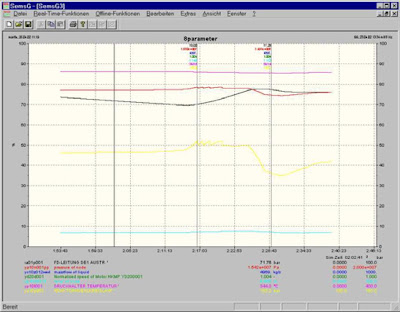
  • Curve Display and Recording Client (CDRC) is used to showonline or offline trending of any analogue variable in the simulation software.Access to the variable is database supported. A set of recorded data may bestored and reloaded later for post-analysis. It can also be exported to standardWindows spreadsheet programs such as Excel.
  • The CDRC is capable ofdisplaying up to 8 variables per screen and up to 10 screens.Each value axis is individually scaleable. The curves show up to four hourshistory. When the curves reach the right border they are automatically scrolledleft.In case of backtracks the curve history is restored from the session archive upto the backtrack entry point followed by a continuous update of the values withactual data from the simulation.

Manjung Simulator System Instructor Station Features

Expert Commands
  • A set of expert commands are available to allow the creation of batch files withinstructor commands. The syntax is easy to understand. The batch files can becreated with any standard editor. In this way it is possible to create scenariofiles for the training sessions.

Tuesday, April 24, 2007

Manjung Simulator System Instructor Station Features


Computer Aided Exercise Client (CAEP)
  • The computer assisted exercise client allows the execution of single instructor commands or of predefined lists of expert commands (batch files). Each command can be triggered by an execution time. The batch files can be created with any standard editor. In this way it is possible to create scenario files for the training sessions.The lines in a loaded batch file can be edited if they are not triggered.

Manjung Simulator System Instructor Station Features

Mobile Instructor Console
  • Optionally a mobile instructor console can be easily connected to the system.The mobile instructor console is based on a Centrino tablet PC with Windows XP Operating system and takes advantage of latest W LAN-technology.Considering the modular approach for the SEMS XP - IS GUI it is possible to execute all available instructor functions on this device. The connection to the simulator LAN is realized via a wireless access point.

Manjung Simulator System Computer Complex


  • The Simulator System will have the hierarchy depicted in figure above. The Man-Machine-Interface (MMI) level will be identical to that of the Reference Plant. The Distributed Control System (DCS) and the various Package Control Systems including MicroRec (turbine control and protection system) are referred to as Control Systems (CS).
  • The Control Systems that the MMI interfaces will be fully emulated, having the capability to exchange information including data and logic between the Simulator System and the Reference Plant Control Systems.The MMI level will use OperateIT including all software and hardware that support the operation of OperateIT. The MMI level will have the capability to exchange information including data and diagram/display mimic between the Simulator System and the Reference Plant MMI level.

Manjung Simulator System Computer Complex


  • The Simulator System will simulate the Reference Plant including the Operator Consoles (Workstations), the Supervisory Consoles (Workstations), the OperateIT Servers, boiler and turbine trip buttons, Hard Panel Soft Simulation and the Sequence of Event Recorder. The DCS Engineering Workstation, the CCTV system and the large screen display will not be part of the Simulator System.The Simulator System will be identical to the topology indicated in figure below.

  • The Simulator System topology comprises of two (2) Simulator System LANs, i.e. the S-Net and the O-Net, both operating at 1000 Base-T or 1000 Mbps, and inter-connected via two (2) Real Time Data Servers (RTDS).

Manjung Simulator System Computer Complex


  • The Simulator System will be connected via proper hard cable communication links to the Reference Plant to provide information exchange capability including data, logic and graphic, both on the Control System level and the MMI level. These links will also enable Configuration or Historian Server in the Simulator System to act as a Supervisory Console of the Reference Plant where the current state of the Reference Plant can be observed but no operation or modification can be done. However, the instructor’s access to the Reference Plant Control Systems will not affect the normal operation of the Reference Plant. The instructor will not be capable in any way of modifying the Reference Plant Control Systems via this method of access.

Manjung Simulator System Capabilities


Schematic and Description of Simulator System Capability for I & C Information Exchange
  • The download of the Distributed Control System (DCS) from the Reference Plant shall be via the translator-tool. The original CAD drawing will be parsed by a translator into simulator format. For the uploading process, the modified simulator CAD drawing (in identical format) will be transferred to the Reference Plant Engineering Work Station (EWS) from the Simulator Engineering Work Station (SEWS) .The modifications of the I & C at the Simulator Engineering Work Station (SEWS) will be done using the original DCS CAD editor. The downloading of the logic or modifications of the I & C shall be only to simulator environment from the SEWS. If the logic or modifications of the I & C is acceptable in the simulator environment, it may be subsequently sent to the Reference Plant Engineering Workstation (EWS) from the SEWS.
  • The Contractor shall configure read-only feature on the Simulator System ABB Operator Station connected to the Reference Plant to fulfill the connectivity requirement, see Schedule 1 Figure 1. The connectivity could be established either online or offline via a fiber optic communication without any effects on the Reference Plant.
  • The upload and download capability for the logic configuration and the read-only feature on the Simulator System ABB Operator Station shall not affect the Reference Plant.

Manjung Simulator System Capabilities


Schematic And Description Of The Communication Between The Operator Stations (A – Part Of O-Net) And Simulation Computer (C – Part Of S-Net) Via RTDS (B).
  • The communication between the Operator Stations (A – Part Of O-Net) And Simulation Computer (C – Part Of S-Net) shall be via RTDS (B) using special client/server application called OPC (Object Link & Embedding for Process Control) that resides in the RTDS and normal networking. The Contractor shall use a Software development package from a company, SOFTING, to create the Software for the OPC Client on Operate IT side and the two OPC servers on simulator side, see B above. The Software development package shall take care of the lower communication levels for example, DCOM or TCP/IP. The lower communication levels shall be created automatically based on the OPC conventions. The Contractor shall create the application Software for the client and the servers only. Client and servers will be configured according to the actual plant data model.
  • For the Operate IT system the Contractor shall obtain the necessary ABB licenses. The Contractor shall also provide full configuration of the Simulator System including the RTDS by downloading Reference Plant data and configuration data in terms of displays and data model. A three man month support by ABB specialist to download and configure the data on the Simulator System Operate IT shall form part of the Contract.
  • The time stamping of signals in the Simulator System shall be identical to that of the Reference Plant and that there shall be alarm server in the Simulation Computer.

Manjung Simulator System Capabilities


Schematic And Description Of Scenario Creation In The Simulator System
  • The method of replay is to capture the operator input (Operator Action Log), and Reference Plant data (in the form of binary data and / or analogue data archived in the Reference Plant RTDS) for the output calculation of the Simulator System response.
  • The binary data and / or analogue data archived in the Reference Plant RTDS shall be loaded from the Reference Plant via the communication link into the SEWS. Here, the data shall be duly converted for the Simulator System environment. Based on that converted data, the cause of the problem is expected to be analyzed by applying various Initial Conditions (ICs) or malfunctions that would bring about or lead to the scenario that happened in the Reference Plant. The final output of applying various ICs and malfunctions is combined with the converted log data (in the form of expert commands) and captured in a simulator scenario file. This simulator scenario file is then run on the Simulator System and compared with that event in the Reference Plant. If the result is unacceptable, a similar iterative process is required but using different Initial Conditions (ICs) or malfunctions.
  • The Simulator System supports an "Input"-Replay. It is a feature where a replay always starts at a defined backtrack entry point and all the operator and instructor inputs which had been recorded during the previous replay recording will be inputted to the Simulator System. This means the models will calculate according each input and will produce the desired output to the hard panel soft simulation and displays. In the IS, the "Input"-Replay can be stopped and continued, repeated or put to “FREEZE”. In the latter case it is possible to continue with normal operation when going into “RUN” again.